No & Type of Engines: Year of Manufacture: Date & Time (UTC): Location: Type of Flight: Persons on Board: Injuries: Nature of Damage: Commander's Licence: Commander's Age: Commander's Flying Experience:
Tail no GPB, BGA 3705 None 1985 17 April 1999 at 1609 hrs Northall, Bedfordshire Training Crew - 2 - Passengers - None Crew - 2 (minor) - Passengers - N/A Aircraft destroyed BGA Basic Instructor's Rating 45 years 1,075 hours (of which some 600 were on type) Last 90 days - 21 hours Last 28 days - 14 hours AAIB Field Investigation
The glider was operating from a gliding site at Dunstable, Bedfordshire, and was being used for a one day training course. At the time of the accident the glider was undertaking the last intended flight of the day for one of two students on that course. In accordance with the policy of the gliding club, both the instructor and student were wearing parachutes and the instructor had briefed his student on the use of his parachute and how to abandon the glider should this be necessary. Thunderstorm activity had been forecast for the area and although a large area of bad weather could be seen to the north of the airfield from which the glider was operating, it was advancing only very slowly towards the local flying area. Heavy falls of rain and wet snow could be seen beneath the advancing cloud line.
The glider had been towed to 2,200 feet agl and for approximately one hour had been soaring at heights up to 4,000 feet in the area between Leighton Buzzard and Bletchley. For the last part of the flight, the glider returned towards the airfield and was flying along the front edge of this large area of cloud, approximately 500 feet above its base, where the air was rising at 2 to 3 kt. The pilot reported that he was in clear smooth air and close to the cloud. Shortly before the accident, other gliders in the area had been returning to the airfield in view of the approaching bad weather. At a local time of approximately 1709 hrs, after the glider had climbed back towards 3,000 feet, the instructor also decided to return to the airfield ahead of the approaching weather and therefore turned away from the cloud. A short time later when he estimated that his course had diverged from the cloud line by some 30°, and they were approximately 2,500 feet agl (some 300 feet above the cloudbase), at an estimated 800 yards from the cloud in clear air and flying at a speed of some 80 kt, the glider was struck by lightning and large sections of its airframe disintegrated.
From that moment, the instructor later stated that his memory was not particularly clear. He remembered hearing a 'very loud bang' and then 'feeling very draughty'; he also believed that he may have momentarily lost consciousness. On recovering, he felt dazed and remembered slowly becoming aware that 'something was seriously amiss' and that this was 'a real emergency requiring unpleasant and decisive action'. He was able to shout to his student in the front cockpit two or three times to undo his straps and abandon the glider but, owing to some impairment of his hearing, the student was unable to hear him clearly. The student had already decided to abandon the glider and, after he had departed, the instructor followed but was surprised when he realised that he had not had to jettison his cockpit canopy. It was estimated that both parachutes had successfully inflated by 1,800 feet agl.
The lightning strike was only witnessed by a few people in the area, but many more saw its immediate aftermath with large items of slowly falling debris, two inflated parachutes, the fuselage descending vertically at high speed and a ball of smoke and fine debris next to the cloud where the glider had been struck. All witnesses reported that the flash of lightning occurred simultaneously with an extremely 'loud crack' and many of these, including one police officer in the centre of the nearby town (Dunstable), expressed the view that it was probably the loudest sound they could remember hearing. It was also recollected by many witnesses that this had been the first lightning flash of a series of discharges which had then occurred in that area over a period of some 15 minutes.
Apart from the damage to the hearing of both occupants, 'sooting' to the upper part of the instructor's jacket, parachute pack and the hair on the back of his head, neither suffered any major injuries as a result of the lightning strike. The student pilot landed on the roof of a disused petrol station adjacent to a busy road in the village of Northall, but escaped major injury. The instructor descended into a nearby field and suffered a broken ankle upon landing. The rescue services were quickly on the scene and both occupants were taken to hospital; the student pilot was allowed to return home later that evening and the instructor was released four days later after surgery to his ankle.
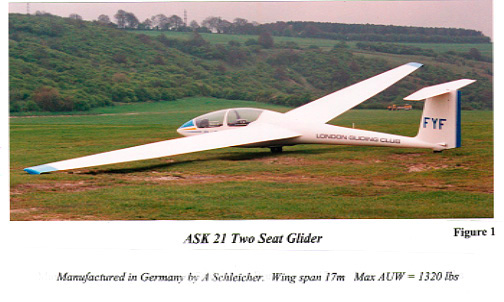
The glider was a tandem two seat closed cockpit sailplane which was constructed almost entirely of glass reinforced plastic (GRP), with foam or honeycomb filled sections bonded together. These materials are electrically non-conductive. It was of conventional layout for a sailplane with a 'T' tail (as illustrated in Figure 1) and was not fitted with flaps. Wing mounted 'paddle' type airbrakes, which move normal to the wing upper surface into the airflow, were installed and were flush with the surface when retracted. The ASK 21 has a wing span of 17 metres, a maximum glide ratio of
1:32 and a maximum all up weight of 1,320 lb. In common with almost all gliders, each wing and the tailplane were designed to be easily disassembled from the fuselage for ground transportation. The wing skins were fabricated from two thin layers of GRP sheet bonded to a rigid foam core and were bonded together along their leading and trailing edges. Whilst the rear wing spar section was simply formed from several layers of GRP, the main spar was more complex. The web of the main spar was constructed in a similar manner to the wing skins and was capped top and bottom with unidirectional GRP tapered sections from root to tip. The elevator, both ailerons and the two airbrake surfaces were all manually operated from the two cockpits by a series of metal levers, push/pull rods and bellcranks. The rudder was connected to the pedals in the cockpits by steel cables.
In common with most sailplanes, there was no designed-in protection against lightning strikes. Since manufacture in 1985, GBP had flown for a total of some 4,000 hours during some 28,000 flights.
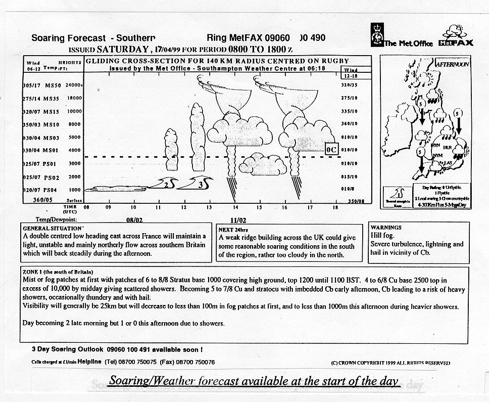
A combined weather and soaring conditions forecast (Figure 2) was obtained by the associated gliding club early on the day of the accident and this was made available to all pilots, including the instructor in GBP. This forecast proved to be reasonably accurate. The general synoptic situation was given as a double centred low heading east across France which maintained a light, unstable and mainly northerly flow across southern Britain that was expected to 'back' steadily during the afternoon. Warnings of severe turbulence, lightning and hail were issued in the vicinity of cumulonimbus (Cb) clouds. Cloud cover for the afternoon was forecast as 4 to 6/8 cumulus (Cu) formations, base 2,500 feet with tops in excess of 10,000 feet by midday, giving scattered showers and becoming 5 to 7/8 stratocumulus (Sc) with embedded Cb during early afternoon leading to a risk of heavy showers, occasionally thundery and with hail.
At the take off time of 1610 hrs, it was reported by the instructor that the cumulus clouds in the area had not greatly developed and were spaced approximately 2 to 3 miles apart in an otherwise clear sky.
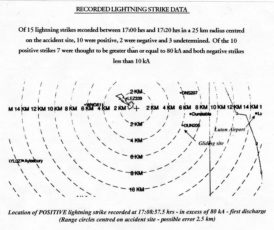
EA Technology Limited, a company which has specialised over the last decade in the monitoring and recording of lightning discharges in and around the UK, was commissioned by the AAIB to supply discharge data for an area of 25 km radius centred near the location of the fuselage wreckage, N 51° 52.45', W 000° 36.85' for the period between 1700 and 1720 hrs local on the day of this accident. Of the fifteen associated discharges recorded, ten were identified as being of positive polarity, two were of negative polarity and three were undetermined. Of the ten positive discharges, eight were recorded to have been in excess of 80 kiloAmps (kA). The first recorded discharge occurred at 1708 hrs and 57.5 seconds; this was a positive discharge in excess of 80kA, the location of which was the closest to the accident site (see Figure 3).
Lightning damage mechanisms
Damage to aircraft from lightning strikes can result from both 'direct effects' and 'indirect effects'. The former is characterised by damage caused by the attachment of a lightning arc to, or the passage of lightning current through, the airframe. Indirect effects relate to damage or the upset of electrical/electronic systems by transient currents and voltages induced by the lightning current. In the subject glider, only the direct effects were relevant, and these could be split into three categories. Firstly, Joule heating generated from the passage of lightning current through conductive components; secondly, localised heat damage and erosion where lightning arc roots attached; and thirdly, the damaging effects of lightning arcs and resultant shock waves and overpressures within the glider structure.
The Joule heating generated is proportional to the time integral of the power dissipated, ie heat = ∫i2.R.dt , where i is current measured in Amps and R the resistance at any point measured in Ohms. The parameter ∫ i2 dt is referred to as the 'Action Integral' in units of Ampere2seconds (A2s), which is equivalent to Joules/Ohm of component resistance, R. Since lightning can be considered as a current source, this parameter is a measure of the energy potential for a particular lightning strike to cause severe Joule heating and arc affects.
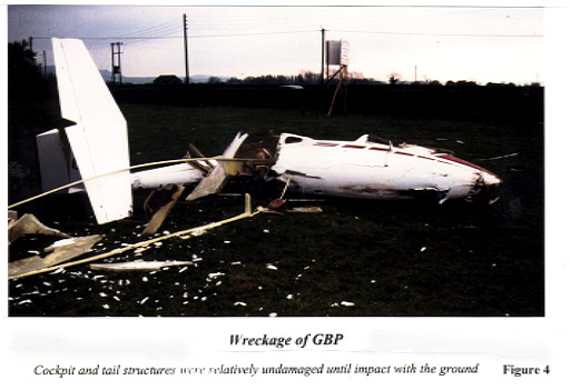
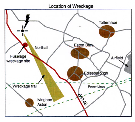
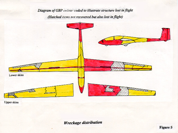
Figure 4 shows a view of the main wreckage shortly after the accident. This comprised the cockpit structure, the tail section, inner section of the left wing, both airbrakes and their operating mechanisms and the main spar caps over their full length. It was readily apparent that almost all of the right wing, the outer section of the left wing and the centre part of the fuselage had detached in flight, much of this wreckage being recovered from an area downwind from the estimated position of the strike on the glider (Figure 5a and Figure 5b). The main spar pinned joint had remained connected and was easily disassembled prior to recovery of the wreckage to the AAIB facility at Farnborough.
Structure
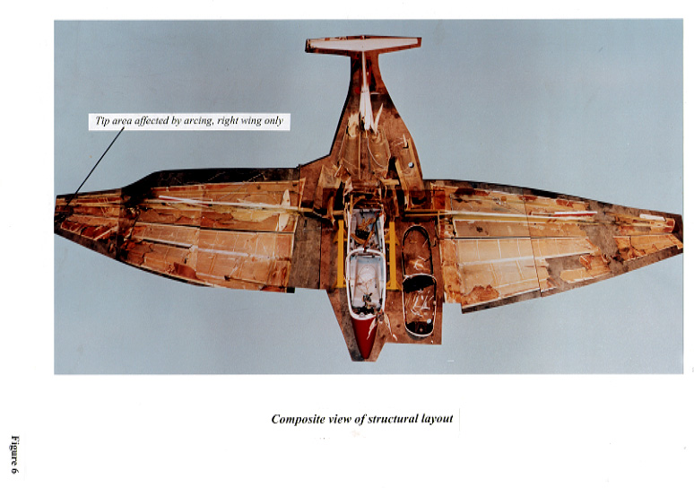
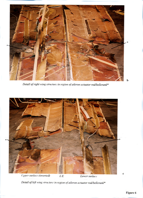
Most of the glider's structure was recovered, with the notable exception of the ailerons where only the outboard section of the left aileron was found. After recovery to Farnborough, the wreckage was laid out in a 2-dimensional reconstruction for detailed examination, as shown in Figure 6a and Figures 6b and 6c. From this examination and the as-found distribution of the wreckage on the ground, it was readily determined which sections of the airframe had separated in flight at the time of the strike. There were four main areas of the glider's structure which had either fragmented, or had been directly affected by internal overpressure and these were also characterised by heavy soot deposits and some metal spatter. They were the fuselage centre section, the right wing tip and the areas aft of the main spar at the inboard end of both ailerons. Sooting was also present along the forward side of the bond line between the right wing tip and the aileron bellcrank bracket attachment bolts. Most bonded joints within the wings, and the bonded seams in the centre of the fuselage, had separated along the adhesive lines. Both cockpit canopy frames had remained securely attached to the fuselage, but all transparency material had fragmented at the time of the strike. Additional damage had occurred to the cockpit and tail section during ground impact. There was no evidence to indicate that any lightning current had passed along the fuselage.
Flying controls All flying control system components in the glider were manufactured from steel or aluminium alloy. Steel generally has a higher value of resistivity and lower values of specific heat and conductivity than aluminium, and therefore for a given current density it is likely to sustain more localised damage from Joule heating. From the examination, it was readily apparent that damage attributable to the lightning strike had only occurred within the aileron system, with evidence of differing degrees of damage present throughout this system. The adjacent airbrake operating mechanism in the wing and centre fuselage, and the elevator and rudder mechanisms, had only been damaged by the in-flight break-up and impact with the ground. (The lack of lightning related damage, particularly to the airbrake operating mechanism, indicated that the strike was likely to have been of positive polarity). As a result of these observations, only the aileron system was examined in detail.
Aileron system
Description
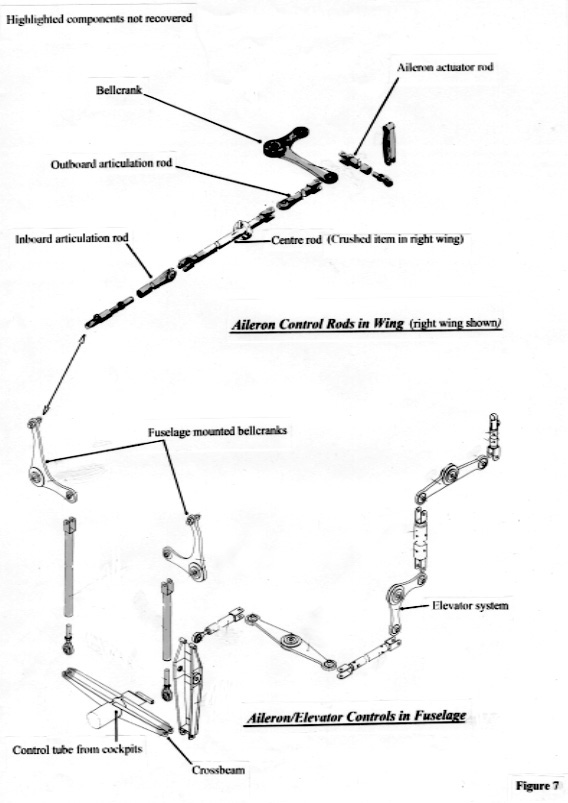
The ailerons were operated by a simple system of levers, rods and bellcranks as illustrated in Figure
7. Pitch and roll inputs from each control column were transmitted through a steel tube to which was welded a fabricated crossbeam. Each end of this crossbeam connected to a short vertically oriented rod, which connected to bellcranks mounted in the fuselage in the region of the wing roots. These in turn connected to aluminium alloy rods in the wings. There were three such aluminium rods in each wing, connected in series with a short articulating rod at each end of a long centre rod constrained to move axially through a series of support rollers. The outboard articulating rod operated another bellcrank, mounted to the rear face of the main spar, and from which an aileron actuator rod operated the aileron surface at its inboard end, some 3.3 m inboard from the wing tip. All joints in this system were either self aligning ball or plain bearings, with the exception of the wing-to-fuselage connections, which were quick release Hotellier ball-and-socket joints.
Examination of the aileron system
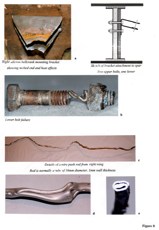
The sections of the aileron operating mechanism that were not recovered from the wreckage trail are highlighted in Figure 7. The recovered items were examined in detail and are described below in sequential order, starting at the right outer wing. The outermost item recovered was the steel bracket which supported the aileron bellcrank. This had remained attached to the spar, but the apex of this bracket, through which the pivot bolt fitted, was missing and it was clear that this had been severely affected by heat as shown in Figure 8a-e. This bracket was attached with three cadmium plated M6 steel bolts, which passed through a hard area on the spar. The bolt heads bore upon the bracket and were secured by nylon insert locknuts which themselves bore against thick steel washers onto the forward face of the spar. Close examination of these nuts and washers revealed evidence of arc attachment and the lowermost of the three bolts had failed by becoming extremely hot and soft in the threaded region, as shown in Figure 8b. Metallurgical examination determined that this section of the bolt had reached a temperature in the region of 1,000°C; it was thus apparent that this bolt had experienced a high Action Integral.
The bellcrank and the outer articulation rod were not recovered but most of the long centre rod, which was made from an aluminium alloy tube of 16 mm outside diameter and 1 mm wall thickness, was recovered in one section. This tube had suffered burning and arc erosion at each end close to its jointed connections, which were missing, and it exhibited an unusual form of damage over its entire length. It had 'collapsed', or had been 'crushed', as a result of the intense magnetic field generated by the conduction of the lightning current, to form an almost solid irregularly shaped 'bar'; this effect is illustrated in Figures 8c-e. Metallurgical examination indicated that the temperature of the rod was unlikely to have risen much above 200°C, and that the folds in the tube wall had retained their original thickness. There was a complete absence of sooting in this middle section of the right wing, indicating that no arc formation had occurred and therefore that this deformed control rod had probably conducted all of the lightning current.
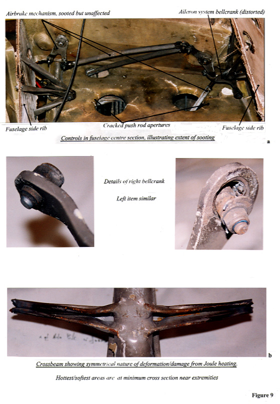
The right inboard articulating rod was missing, but both fuselage mounted bellcranks had remained attached to their support brackets. However it was notable that both of these bellcranks had been deformed in an identical fashion, but not by ground impact. Both bellcranks also had their Hotellier 'balls' missing and both self aligning ball bearings were burnt out, as illustrated in Figures 9a and b. The pivot bearings in these bellcranks were undamaged. The two vertical push rods connected between these bellcranks and the crossbeam were also missing, as were the two fork ends of the crossbeam itself, where there was evidence of severe heating and softening/melting of the steel, as illustrated in Figure 9b. There was some evidence to indicate that the two vertical rods had been forced outwards, inducing damage to the edges of two holes in the structure through which they had passed. Such repelling of adjacent conductors in which high currents flow, in opposite directions, is characteristic and a similar mechanism was also considered responsible for the deformation of the two bellcranks described above.
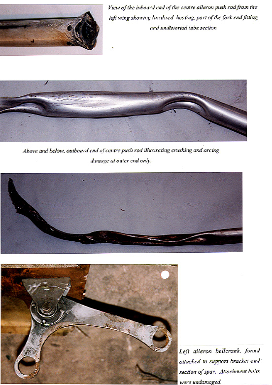
Although there was no evidence of lightning attachment elsewhere in the centre fuselage, the long centre rod in the left wing, which was the next component in the system available for examination, did not exhibit the same damage characteristics as its partner from the right wing. The remnants of the inboard joint remained attached to this rod, although it had been severely heated, but over most of its length it had suffered damage only from the wing structural failure and ground impact. However towards the burnt and eroded outboard end, indications of collapse were present, as shown in Figure 10. The last components examined in this system were the left aileron bellcrank and its support bracket, to which it had remained attached. These were only slightly heat damaged, but the self aligning ball bearings at the ends of the two arms were both missing.
The AAIB had previously investigated an accident to an AS332L Super Puma helicopter, G-TIGK, which had been struck by lightning whilst operating over the North Sea on 19 January 1995 (Aircraft Accident Report 2/97). This helicopter had been forced to ditch in the open sea as a result of tail rotor damage and consequent almost total detachment of the entire tail rotor/gearbox assembly, but had remained upright and afloat in heavy seas allowing all eighteen occupants to escape in one of the dinghies. The main and tail rotor blades on this helicopter were manufactured from carbon fibre reinforced plastic (CFRP). The first causal factor in that report stated that 'One of the carbon composite tail rotor blades suffered a lightning strike which exceeded its lightning protection provisions, causing significant damage and mass loss'. In addition, lightning specialists at Lightning Test & Technology (LTT) at Culham, who had assisted in that investigation, stated that the subject tail rotor blade was likely to have suffered a lightning attachment with an associated Action Integral energy level which could have been some three times the Action Integral level of present lightning certification standards (see later). Concern was expressed in the report that the present Advisory Criteria, AC 20-53A, used for the lightning certification testing of aircraft, appeared inadequate particularly in terms of the level of Action Integral specified for such testing. An associated Safety Recommendation (No 4.8) in the AAIB Report on that accident therefore urged an increase in the specified Action Integral used for lightning certification testing 'to a level compatible with the highest energy positive polarity lightning discharges likely to be encountered in service'. In view of these previous findings and reactions to that Report and the latter Safety Recommendation, it was recognised that this accident to GBP afforded a significant opportunity to further investigate and document the energy characteristics of another suspected high energy strike to an aircraft in the UK. In addition, it was considered that a thorough investigation could highlight to the manufacturers and operators of gliders the mechanism by which this glider was destroyed.
Article 8(2)a of the UK Air Navigation Order provides that the normal requirement for an aircraft to possess a valid Certificate of Airworthiness (C of A) does not apply to a glider on a private flight. However, almost all gliding in the UK takes place under the auspices of the British Gliding Association (BGA), which regulates the sport and requires all gliders operating from BGA affiliated sites to possess a valid BGA C of A. Although gliders are regarded as sporting aircraft and the investigation of accidents to such aircraft is normally delegated to the relevant sporting aviation body, in this case the BGA, in view of the above considerations the AAIB undertook this investigation.
The most recent known severe lightning strike to a glider in the UK occurred to a LS-4 glider on 31 July 1988. Despite receiving a shock from the control column, the pilot managed to land the glider. There was severe delamination of the left wing tip and aileron, and delamination of the elevator trailing edge. The right wing tip had many holes of several mm in length present in the surface. The examination of that glider concluded that the lightning discharge had traversed through the glider, wing tip to wing tip, and that arcs had formed within the wing. The explosive forces generated by these arcs were sufficient to cause the delaminations.
Lightning discharges usually originate from charge centres in a cloud, particularly cumulonimbus clouds, although they can occur in other atmospheric conditions. The charges in clouds are produced by complex processes of freezing and melting, and by movements of raindrops and ice crystals involving collisions and 'splintering'. Typically, most positive charges accumulate at the top of cumulonimbus clouds, leaving the lower regions negative, although there may be a small positive region near the base of such clouds. During their process of development, thunder clouds may extend vertically to over 14 km and their associated strong electric fields can initiate high current discharges. These fields exist before and during a lightning discharge and may extend up to some 10 km from the cloud or charge centre. They initially result in ionising breakdown of the air to form an 'arc leader', but may also cause breakdown of dielectric materials on an aircraft. The magnitude of these fields is dependant upon air breakdown thresholds and range between 400 and 3,000 kilovolts (kV)/metre (m), with rise rates of up to 1,000 V/mm/microsecond( µs).
Lightning discharges may be of three types:-
Flight tests previously carried out in the USA and France with suitably instrumented aircraft have indicated that, generally, inter or intra-cloud discharges are less severe than discharges to or from the ground (or sea), certainly with respect to rise rate, peak current, charge transfer and action integral, the main parameters for quantifying lightning discharges However, such measurements show some evidence that over a portion of some pulse wavefronts, the rise rate for a short period (less than 0.4µs) may be higher than the figure related to cloud/ground flashes. Over 90% of all flashes are thought to occur intra-cloud.
A positive discharge lowers positive charge to earth whilst a negative one lowers negative charge. It is common for a positive flash to comprise only one discharge, whilst negative flashes discharge several charge centres in quick succession, with the result that that the flash contains several distinct pulses of current, and these are usually referred as 'strokes'.
The process that culminates in a lightning flash begins with the formation of an ionised column, called a 'leader', which travels out from a region where the electric field is sufficiently high in field values that it initiates progressive breakdown. This critical field is thought to be about 900 kV/m for water droplets, or 500 kV/m for ice crystals. For a negative discharge to earth the column advances in 'zigzag steps' (a 'stepped leader'), each about 50 m in length and separated by pauses of 40 to 100 µs. The diameter of a stepped leader is between 1 m and 10 m although the current involved, which is low (approximately 100A), is probably concentrated in a small ionised core of about 1 cm diameter. The average velocity of propagation is 1.5 x 10⁵ m/s and this leader may form branches on its downward path to the ground. When it is near the ground it causes high electric fields to form at projections such as trees and buildings and these send up leaders, one of which will make contact with the tip of the downward propagating leader. This has the effect of 'closing a switch' and the position in the lightning conduction channel where this occurs is known as the 'switching point'. When this occurs, a return stroke is initiated which retraces and discharges the leader channel at a velocity of some 5 x 10⁷ m/s and this is characterised by a current pulse of great amplitude and high luminosity. After the first return stroke, further strokes may occur as higher areas of negative charge regions are discharged; the leaders for these usually follow the same path as the first, but in one continuous sweep at a velocity of some 2 x 10⁶ m/s.
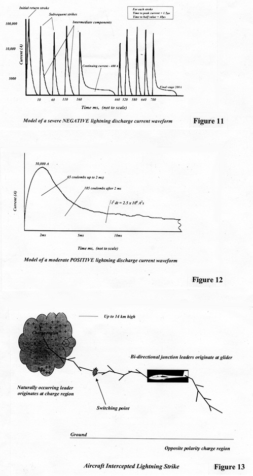
An example of the time history of the return stroke current in a severe negative discharge is shown in Figure 11. The number of strokes in a negative flash is usually between 1 and 11, the mean value being 3; the maximum number can be up to 24. The total duration may be between approximately 20 ms and 1 second., with a mean value of 0.2 second. The time interval between strokes is typically about 60 ms. There is some correlation among these parameters, the flashes with the most strokes tending to be the longest duration. The rise time of the subsequent strokes tends to be lower than the first stroke (typically 2 µs) although the rate of rise is higher, and they can therefore be significant for inducing voltages in, for example, wiring where the inductively coupled voltages are proportional to the rate of change of the lightning current.
Positive flashes to ground had been thought, in the recent past, to occur generally less frequently than negative flashes (approximately 10% of all strikes), but recent research has indicated that in certain geographic locations and in higher latitudes the proportion may be very much higher. Positive flashes are generally more damaging than negative flashes and may be initiated by upward moving leaders. They can occur more commonly over mountains rather than flat ground and normally consist of only one stroke. They have slower rise times than negative flashes, with high peak currents and charge transfer; the duration is longer than a single stroke of the negative flash but usually shorter than a complete negative flash. The stroke may be followed by a continuous current. Typically, the rise time of a positive flash is 20 µs and the total duration 0.1 second. An example of the time history of a positive flash is shown in Figure 12 and this represents a moderately severe example.
The probability of a lightning strike to an aircraft depends on various parameters, e.g. the local climate, flight profile and the type of aircraft. From a significant sample of reported strikes to large transport aircraft operating in scheduled airline service, the average probability of a strike has been estimated to be one in every 10,000 flight hours. This is based on reported events which get noticed because of the bright pulse(s) of light, loud noises or associated physical effects. Other strikes undoubtedly occur, but may go unnoticed or may not be reported. During the time that the lightning channel is attached to any of the aircraft initial attachment points, currents will be flowing in the aircraft. (The completed lightning channel in the air is somewhat stationary and, if the speed of the aircraft is high, the associated arc may sweep back over a surface and re-attach at 'dwell points', causing further local damage. However this effect was not considered to be relevant with GBP due to its relatively low airspeed). In an aircraft of conventional (metal) construction, these currents will distribute among all electrically conductive skins and structural elements between entry and exit locations resulting, usually, in a low current density away from the immediate area of the attachment point.
Some currents may also attempt to flow through, or be induced in, non-structural components such as push rods, hydraulic lines, piping, electrical cables and electronic units etc. This is the main reason that aircraft are electrically bonded so that such (relatively small) currents may pass through the aircraft unimpeded. In aircraft or gliders constructed from a non-conducting material such as GRP, the lightning arc is likely to attach to the extremities of any linked conducting components within that structure. These are likely to be the flying control mechanisms in the wings and/or fuselage, but there is a distinct possibility that a lightning arc may track within the structure before being conducted through such mechanisms. Such arcs ionise the air and almost instantaneously produce extremely high gas temperatures which may be in the region of 50,000°F. The resultant combined shock wave and explosive overpressure emitted from the lightning arc channel can be very damaging to the structure. Additionally, heating damage and failures are likely to occur at various locations wherever resistance or impedance is high relative to the current flowing. This occurs particularly at bearings and joints within a mechanism, with further arcs (and their consequent shocks and overpressures) forming in the opened gaps between the linkages. Large mechanical forces are also generated by the intense magnetic fields associated with such high currents, which may both assist any linked components to separate, thereby inducing further arcs, and/or cause them to deform.
A naturally occurring lightning strike begins when a lightning leader, which originates at a cloud charge centre, happens to approach an aircraft and this interaction can happen for all types of discharges, ie inter-cloud, intra-cloud and cloud/ground (or sea) discharges. When this happens, the electric field associated with charge in the leader intensifies around the aircraft extremities and associated discharges, called 'junction leaders', emanate from these areas. Propelled by the electric field, these junction leader discharges propagate in the general direction of the lightning leader and one, but sometimes more, of these junction leaders may connect with one or more branches of the lightning leader (see Figure 13). An aircraft surface from which a junction leader emanates thus becomes the initial lightning attachment point. Often this is referred to as the initial attachment, or 'entry point'. At the same time additional junction leaders, originating at other extremities, propagate away from the aircraft in the general direction of a region of opposite polarity charge. This may be the earth, or it may be a cloud charge region of opposite polarity. The location(s) from which these leader(s) leave the aircraft constitute other lightning attachment locations, often referred to as 'exit points'. Lightning entry/exit locations occur, typically, on aircraft at airframe extremities such as the nose, wing and empennage tips, tail , in addition to propellers, rotor blades and also engine nacelles.
An aircraft induced strike may result when the aircraft enters an electric field associated with charged cloud regions and the field intensity about the aircraft's extremities is sufficient to initiate and propel, or 'trigger', bi-directional leaders from these extremities. These leaders propagate from the aircraft between regions of opposite polarity charge, and conduct lightning currents through the aircraft, as occurs with naturally occurring lightning. The locations from which the bi-directional leaders originate are also called entry and exit points and there is no generic difference in the characteristics of these points. The terms are used only for convenience in describing the overall lightning process and are perhaps more relevant to a naturally occurring strike, wherein the entry location is associated with the initially approaching leader and the exit location the place from which the leader propagates.
It was not established if the strike to GBP was an intercepted or induced strike, but the effects on the glider would have been similar.
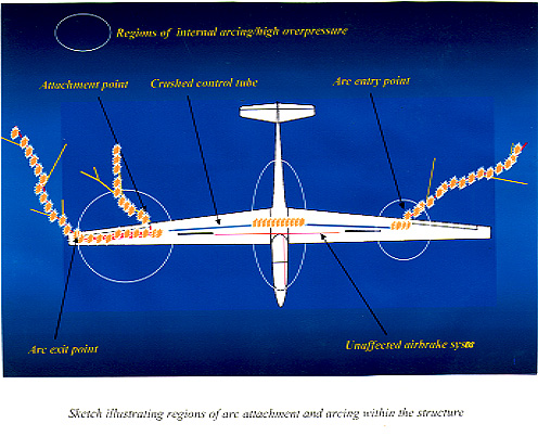
The evidence of damage caused by this lightning strike, and the recorded lightning data, indicated that it had been a positive polarity strike of high magnitude which had entered the glider at the left aileron actuator rod and exited via the tip region of the right wing and the right aileron actuator rod (Figure 14). It was considered likely that in the right wing a junction leader had propagated outboard from the nuts of the three bolts attaching the aileron bellcrank support bracket mounted on the rear of the main spar. This junction leader had tracked along the intersection of the forward face of the rear spar and lower wing skin before puncturing and exiting through the upper wing skin, near the tip. (A similar scenario had occurred in the previously mentioned strike to the single seat GRP glider in the UK on 31 July 1988, but at a much lower energy level). It is known that for even moderate lightning strikes of, for example, 20 kA that overpressures of several atmospheres occur near to the arc. It was also considered likely that a leader had exited from the aft end of the right aileron actuator rod, but since this rod was not recovered this could not be directly confirmed. However, given the extent and similarity of structural damage to that on the left wing, aft of the spar, the available evidence suggested that a leader had in fact emanated from the end of this rod and that at least part of the return stroke attached at that point. The enclosed arc within the wing structure between the three bolts and the tip area, produced by part of the return stroke, would have produced a combined shock/overpressure which appeared to have failed the bonded joints and shattered the upper wing skin local to the wing tip. Slipstream effects were also considered to have generally assisted the structural disintegration once the process of delamination had begun.
Between the aileron actuator rods in the right and left wings, the interconnected linkages of the aileron control system provided a continuous conductive path, albeit with various joints and connections of higher resistance/impedance than the rods or bellcranks. All of these joints had been seriously damaged or destroyed. Although these linkages could have survived a strike of much lower energy (as in the 1988 event), the forces induced by the intense magnetic fields associated with the high currents in this strike had forced apart and distorted many components and were responsible for the remarkable 'crushing' phenomenon apparent on the aileron centre push rod over its entire length in the right wing.
The subsequent arcs which formed in the opened gaps in the aileron linkage, all of which were associated with joints in the system, had resulted in shocks, overpressures and consequent adhesive bond and material failures throughout the wings and centre fuselage. Both canopy transparencies had been blown out by the same overpressure pulse, which destroyed the fuselage central structure, the blast travelling forward from that area to impinge upon the instructor's head and upper parts of his jacket and parachute. The break-up of the left wing was less complete than the right, although delamination of the inboard wing had occurred from overpressures generated in similar locations to that on the right wing. The tip region was different to the right wing in that there was no evidence of arcing outboard of the aileron actuator rod and this region appeared to have delaminated in large sections as a result of the overpressure generated in the area of this rod.
Because of the few conductive paths within the right wing of this glider which exhibited distinctive signs of lightning damage, and the lack of arc tracking evidence (sooting), it was possible to be confident that the crushed control rod from the aileron control system in the mid section of the wing had experienced the entire current waveform of the strike. The failed bracket attachment bolt had clearly experienced a high Action Integral, but it was not certain that it had been subjected to the complete current waveform since its two partner bolts has also sustained arc damage, and it was also considered likely that a proportion of the lightning discharge had entered the bracket through the aileron actuator rod. This failure should, therefore, have been an indicator of the minimum energy available and, by the testing of identical bolts and control tube sections to similar levels of damage, enable the energy of this strike to be quantified within upper and lower boundaries. Such tests to establish the action integral of the strike to GBP were carried out at three different lightning test establishments in the UK, USA and Germany, as detailed below.
This bracket was secured by three M6 bolts which passed through the spar. Evidence was present of arc attachment to the three exposed nuts and washers on the forward face of the spar from an arc which had travelled from the right wing tip within the outer wing. There was arc induced erosion on all three bolt heads, but the lowermost of the group had been subjected to a high Action Integral and its core was determined to have been heated to at least 1,000°C
Simulated lightning discharge tests conducted on similar bolts replicated the latter damage at an Action Integral of some 5.2 x 10⁶ A2s. However, when a bolt taken from the left wing of GBP was also tested, no damage was observed at an energy level of 5.4 x 10⁶ A2s. Although the measured resistance value of this bolt was very similar to the failed bolt, its resistivity was slightly less. In view of this test result, the damage energy threshold of the bolt appeared to be 5.4 x 10⁶ A2s. Since the other two bolts had also conducted current, the total applied Action Integral must have been greater. Estimations of this value were made in two ways. The temperature that the two upper bolts had experienced was estimated from metallurgical examination as being no higher than 200°C. If the arc had 'jumped' from bolt to bolt then the calculated Action Integral for each bolt would have been:-
AI bolts 2 and 3 ≈(200°C/1000°C) x 5.4 x 10⁶ A2.s ≈ 1.0 x 10⁶ A2.s
The total Action Integral would then be at least the simple sum of all three, ie 7.4 x 10⁶ A2.s. However, if the arc had simultaneously conducted onto all three bolts, then this value would have increased to a maximum of:-
√ AI bolts 1,2 and 3 √ AI1 + √ AI2 + √ AI3 ≈√ 5.4 + √ 1.0 + √ 1.0
The latter scenario gave a total Action Integral of approximately 19 x 106 A2s. Thus the possible range of Action Integral for the strike, calculated from the damage to the bolts alone, was bounded by the following two values:
7.4 - 19 x 106 A2s.
The aileron centre control tube from the right wing had been severely crushed over its complete length. Somewhat surprisingly, the corresponding tube from the left wing exhibited little or no such damage, despite there being no evidence that the main current path had not involved both tubes. Attempts were made to replicate the same type of damage at the LTT Culham laboratory using new stock tube of the same specification. A test Action Integral of 5.5 x 10⁶ A2s and a peak current of 270 kA were achieved, but there was no noticeable crushing of any of the tubes tested. A tube which had been deliberately dented became slightly more deformed during tests at these levels, but the effect was slight. Also, in a test where two tubes 45 mm apart jointly shared the current (simulating the possible effect of current also flowing in the parallel airbrake linkage), the tubes were strongly attracted and crushed against each other, however no evidence of this effect was apparent in the wreckage, supporting the view that all of the current had been conducted through the crushed rod.
It was therefore evident that an Action Integral and/or peak current well in excess of those applied in these tests was responsible for the damage which occurred in GBP. It is worth noting that whereas the heating effects on the bolts and bracket would only have been related to Action Integral, the damage to the control tube was likely to have been a function of both the (peak current squared) and the (Action Integral). Whilst the instantaneous force resulting from an associated magnetic field is proportional to the square of the current, the compression of this rod must have resulted from the force having been applied for a required finite time.
Similar tests conducted by Lightning Technologies, Inc. in the USA achieved higher Action Integrals of up to 7 x 10⁶ A2s, but did not reproduce the crushing effect. Further comprehensive testing carried out by the E7 Electrical Institute at Munich University in Germany achieved very high Action Integrals of up to 17.4 x 10⁶ A2s with a peak current of 312 kA, but again without any significant reproduction of the crushing effect. Deliberate pre-test deformation of a test sample was slightly enhanced in a test which achieved an action integral of 15.3 x 10⁶ A2s with a peak current of 261 kA.
Right aileron bellcrank attachment bracket
Calculations were made to estimate the Action Integral associated with the failure of the aileron bellcrank support bracket in the right wing, which is shown in Figure 8a. This had been subjected to heating damage, more pronounced towards the apex, where the lower cross-sectional area had resulted in a high current density. The bracket had failed in this region as a result of melting/softening of the steel, releasing the aileron bellcrank. An estimation of the cross-sectional area at the point of failure, based on measurements made of the bracket from the left wing, indicated a value of 30 - 35 mm2. The cross-section of the failed attachment bolt was determined as
19.6 mm2 and, as previously described, testing of a similar attachment bolt from the left wing indicated a damage threshold Action Integral of 5.4 x10⁶ A2.s . As heating effect is proportional to action integral/area2, and making the assumption that the steel bracket had similar properties to the steel bolts in terms of resistivity, specific heat and thermal conductivity and that a similar softening temperature of approximately 1,000°C had been reached, then the action integral required to fail the bracket would have been:
(30 - 35/19.6)2 x 5.4 x106 A2.s ≈ 12.5 - 17 x 106 A2.s
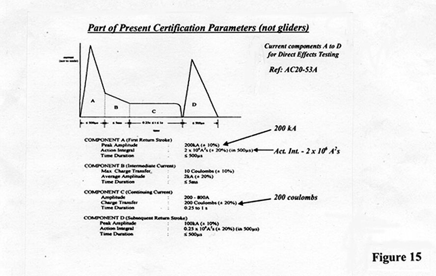
It is possible, however, that because of the very large magnetically induced forces involved, the bracket may have failed before a high degree of softening had taken place, and the Action Integral could therefore have been proportionally lower with a lower temperature of failure than the 1,000°C assumed.Certification standardsCertificated fixed wing aircraft and helicopters are required to withstand lightning strikes without sustaining significant damage and this must be demonstrated in lightning certification testing of associated aircraft structures and components through simulated lightning strike tests which generally apply specified (Advisory Circular) energy levels. These 'Advisory Circular' standards are intended to assist manufacturers in conducting such lightning certification testing, and provide an external idealised lightning environment with associated test parameters. Advisory Circular AC 20-53A, which was issued on 4 December 1985, is still the industry lightning standard and specifies several current components (waveforms) which may be used to achieve certification. The current components, annotated A to D, which comprise the present AC 20-53A waveform for evaluating the direct effects of lightning are shown in simplified form in Figure 15. Such waveforms represent idealised lightning environments, which are applied to aircraft for the purposes of analysis and testing. The waveforms are not intended to replicate a specific lightning event, but are intended to provide composite waveforms which model the effects of natural lightning on aircraft. The present certification standard, AC 20-53A, was intended to provide adequate levels of lightning protection against some 98% of cloud to ground strikes, if it is assumed that 10% of these are positive discharges. However it may be noted, by contrast, that in the actual storm in this accident at least some 66% of the recorded discharges were of the more damaging positive polarity. With reference to Figure 15, component A is the first return stroke and represents a combination of the severe parameters of both the positive and negative first return strokes. Component B is an intermediate current, component C the continuing current and component D a subsequent return stroke. Various parameters are defined in AC20-53A, three of the most important being the applied Action Integral value of 2 x 10⁶ A2s, Peak Current of 200 kA and Charge Transfer of 200 coulombs.
DiscussionThe most significant factor in the loss of this composite structure glider was the formation of lightning arcs within the enclosed volumes of the wings and fuselage, which caused structurally damaging shock waves and high overpressures that induced in flight structural disintegration of the glider. In conventional 'metal' aircraft, the lightning current is generally conducted through the metallic structure where the cross-sectional area at any point is usually more than sufficient to ensure a low current density. Failures of the conducting path do not usually occur and therefore arcs do not form. However, such aircraft are required to show by test and calculation their ability to withstand, with minimal damage, the previously described lightning energy levels for certification. It is not unknown, however, for discharges with much higher energy levels to strike aircraft, as indicated by the accident to the AS332L Super Puma, G-TIGK, which ditched in the North Sea on 19 January 1995. The action integral in that particular strike was deemed by LTT Culham to have been approximately three times the level that certification Advisory Criteria AC 20-53A specifies. The tests and calculations carried out in support of this glider investigation indicated that the associated Action Integral probably lay between values of 7.4 x 10⁶ A2.s and 19 x 106 A2.s, based upon the damage/calculations to the bellcrank bracket and attachment bolts. It was initially considered that another assessment of the applied Action Integral value could be obtained from lightning simulation tests using identical samples of the aileron control rod, which appeared to have conducted all of the lightning discharge current in the strike, although the tube collapse was likely to be linked more to peak current than action integral. However, similar characteristics of crushing and distortion could not be reproduced, even at very high Action Integrals of up to 17.4 x 10⁶ A2s, with peak currents of 312 kA. There are, reasonably, doubts as to whether such laboratory testing can always accurately reproduce the detailed effects of natural lightning. It was possible that factors such as the manner in which the discharge current entered and exited the rod, the way in which it was supported and subtle differences between the rods in the glider, pre-accident, and the test articles, could have resulted in differences in damage characteristics. However, notwithstanding such reservations, the ranges of Action Integral achieved during these tests (ie 7.4 - 19 x 106 A2s, with a mean value around 13) or derived by related calculation were very much higher than both the strike to the Super Puma mentioned (a factor of around 4) and the AC20-53A Action Integral standard (a factor of around 6). It is considered, therefore, that these findings have indicated that there is little doubt that the positive polarity lightning strike which occurred to this glider was massive in comparison to the present external idealised lightning environment used to evaluate protection systems on aircraft for certification purposes.As previously stated, there are no existing requirements for lightning protection in the design of modern gliders and consequently few designs, if any, are protected. The mechanism by which this glider was destroyed was reasonably well resolved, although this event would seem to represent a rare example of an extremely high energy strike to a completely unprotected structure. The data contained in this report should provide additional information to assist certification authorities, designers and manufacturers of aircraft, including gliders, when considering new certification standards and methods of mitigating the worst effects of high energy discharges through composite structures. In addition, this accident highlights the inadvisability of flying unprotected composite aircraft in close proximity to thunderstorms and the prudence of wearing parachutes in such composite gliders. Many more recent glider designs use CFRP for major structural elements. CFRP is an electrically conductive material, but is more resistive than aluminium alloy. Modern jet transport aircraft types are also designed with increasing utilisation of such composite materials for structural and control surface elements. One example of this trend is the Boeing 777 which uses CFRP for the horizontal and vertical stabiliser torque boxes, and graphite epoxy for the elevators, rudder, ailerons and flaps. The structurally damaging effects of high energy strikes on smaller and insufficiently protected CFRP structures (rotor blades) are well illustrated in the report on the accident to the AS332L Super Puma, G-TIGK, which occurred over the North Sea on 19 January 1995 (AAIB Report 2/97). However it is notable that the highly energetic positive lightning discharge which destroyed this glider did not occur over the higher latitudes of the North Sea as in the above accident, but over land only some 25 nm to the north of London Heathrow Airport. Safety recommendationsThis composite structure glider suffered in flight structural disintegration as a result of internal arc shock wave/overpressure effects generated within the wing and centre fuselage volumes by a positive polarity lightning strike. The Action Integral energy level of this strike was assessed, by test and calculation, to have been at least some 8 to 9 fold higher than the Action Integral level specified in Advisory Circular AC 20-53A which lightning certificated aircraft are currently required to tolerate with minimal damage. The fact that the glider had no lightning protection systems, and was not required to be so protected, was a factor in this accident. Although this type of in flight structural disintegration appears to have been a unique event, in view of the wide use of CRP in modern gliders and the continuing use of metal control system components, it is considered that manufacturers should develop new methods of minimising structural damage to gliders following lightning strikes. In its response to the Draft copy of this Bulletin the German manufacturer of this glider, Schleicher, mentioned the possible benefits of inserting non-conductive push rods close to the control circuit ends in an endeavour to reduce the susceptibility of metal control system extremities to lightning discharge attachment. In its response, the BGA speculated on the improved lightning protection which non-conducting composite material control push rods might provide.
In addition, lightning strikes of the energy levels associated with this discharge raise concerns in relation to the ability of lightning certificated aircraft to withstand such strikes without significant damage. At the present time the standards contained in the Advisory Circular AC 20-53A are under international review and one of the objectives of this review is to examine the implications of raising the value of the applied Action Integral above its present recommended level of 2 x 10⁶ A2.s. In this context it is notable that despite the very high Action Integral values achieved during testing in this investigation, the tests still failed to reproduce similar damage to the aileron control rod which was thought to have conducted all of the lightning discharge current in this strike.
As a result of the above findings and considerations, the following Safety Recommendations are made:
It is recommended that the British Gliding Association request glider manufacturers to develop new methods of providing protection for present and future glider designs against the potentially critical effects of high energy lightning discharges upon metallic control systems and composite material structures. Recommendation No 99-49It is recommended that the CAA should request serious consideration, during its participation in the current international review of aircraft lightning certification standards, of the fact that energy levels from positive polarity discharges have been shown to greatly exceed those specified in Advisory Circular AC 20-53A, with the associated implications for the certificated lightning protection assurance of existing and future aircraft designs, particularly those which utilise significant amounts of composite material in their primary and control structures.
References:- Reports of EUROCAE WG-31 and SAE Committee AE4L, AE4L-97-4 and AE4L-98-5