The Compact Heavy Ion COunter (CHICO) is comprised of two equivalent halves referred to as the upstream and downstream detectors (as seen from the particle beam’s point of view). Each half consists of twenty segments which are gas-filled volumes separating a positive (anode) plate and a negative (cathode) plate. Ions traveling through the gas create free charges that are collected at the plates resulting in the generation of small signals. To be useful these signals require amplification to a level suitable for use in the data acquisition systems. The electronics to perform this amplification are referred to as CHICAs for Charged Heavy-Ion Counter Amplifiers. From this point forward the term CHICA will be defined to be: "one of the twenty printed circuit boards mounted with the CHICO detector for the purpose of amplifying the detector’s signals. Each printed circuit board is comprised of four input and four output channels.".
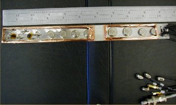
Photo of amplifier board with shielding removed.As stated earlier, each of the forty detector segments within CHICO have an anode and a cathode for a total of eighty plates. The small signals on these plates will be amplified by CHICAs and produced as timing signals.
The entire CHICA system has a total of 80 channels of input from the CHICO detector, and 80 channels of output to the data acquisition system. The input signals are anticipated to be on the order of 1 to 2 millivolts. The system is designed to operate with signals possessing a leading edge rise-time near 500 MHz. The cathode channels will provide approximately 60 Decibels of amplification with signal inversion and the anode channels a non-inverted 50 Decibels. The timing output on all channels should be approximately 1 to 1.5 volts. These values have been determined by previous experiments utilizing the Coulex detector at Rochester.
The CHICA amplifiers are required to be physically close enough to the CHICO detector to capture the CHICO output signals while they still have enough amplitude to be usable. This demands that the amplifiers be situated in an available space that limits the physical size of the amplifier assembly to 10.5 inches in length and requires that the array "wrap around" the beamline adjacent to CHICO. To accomplish this it has been decided to break the array up into twenty identical printed circuit boards, each board containing two cathode and two anode input channels and two cathode and two anode output channels. Ten of these boards will then be used to wrap around the beampipe upstream of CHICO, and ten downstream to complete the entire system.