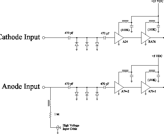
Compact amplifier boards were designed at the Nuclear Structure Research
Laboratory specifically for use with the CHICO detector. Each PPAC has a
dedicated amplifier board with two anode channels and two cathode channels.
The physical size of the boards was kept small, 26.7 cm by 3.2 cm, allowing
them to be housed in the detector assembly as close to the PPAC detectors as
possible to reduce electronic noise pickup. The amplifiers are based on
cascadable microwave amplifier chips, simplifying the design and
construction. A schematic diagram of the amplifier circuits is shown in
Figure 8. The amplifier circuit boards are three-layer boards,
with the signal traces on the middle layer shielded by ground planes. Since
the acquisition electronics require negative inputs with pulse heights on the
order of a Volt, the anode amplification chain is non-inverting with a total
gain of 400, while the cathode amplification chain is inverting with a gain of
700. The 500 MHz bandwidth of the amplifiers ensures that the rise times of
the pulses are not degraded during amplification. A photograph of one
amplifier board is shown in Figure 7. The geometrical
arrangement of transmission lines and amplifier boards is illustrated in Figure
1.
 |